Next Post
Mosaic Writer
Learn how to use Carmenta Engine 5.17's MosaicWriter to stitch georeferenced drone video frames into GeoPackage mosaics for real-time mapping applications.
View PostFollowing the article Getting started with the tactical symbology in Carmenta Engine, we will explore how to set up your application to support tactical graphics.
Tactical graphics belong to the tactical symbology and are part of our Tactical Extension, at the time of writing this article Carmenta support the following military extensions:
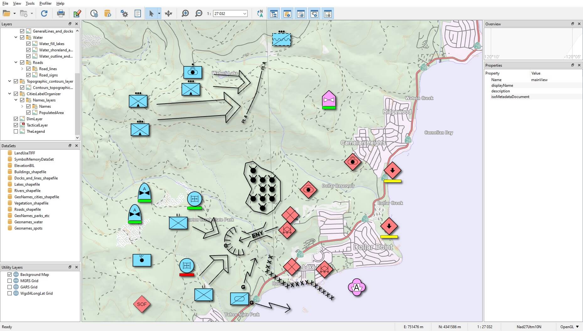
You can take a look at the sample tactical_map.px provided with the SDK, it showcases some visualizations and attributes for some symbols:
Just as for the tactical symbols in our previous article, we use the TacticalVisualizer to visualize tactical graphics. The components that will make up our configuration are:
TacticalLayer.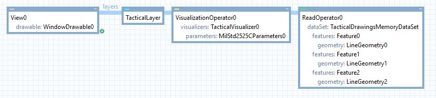
Using the createTool or createTouchTool you can set the necessary MilStd2525CCreateToolParameters to create Tactical Graphics:
// Configure a CreateTool on a MapControl to create a MIL-STD-2525C Main Attack corridor
static void CreateMilStd2525CSymbolWithTool(
    MapControl& mapControl, MemoryDataSetPtr memoryDataSet)
{
    // Initialize a create parameters class for the Appendix B "Main Attack" line
    MilStd2525CCreateToolParametersPtr createParams =
        new MilStd2525CCreateToolParameters("G-GPOLAGM-----X");

    // Create the tool and activate it in a MapControl
    CreateToolPtr createTool = new CreateTool(memoryDataSet,
        new AttributeSet(), createParams);
    mapControl.tool(createTool);
}
Internally, the tool will be configured based on the MilStd2525CCreateToolParameters and is now ready to be used. Of course, if you’re using another military standard you will have to replace the ToolParameters with the one you need.
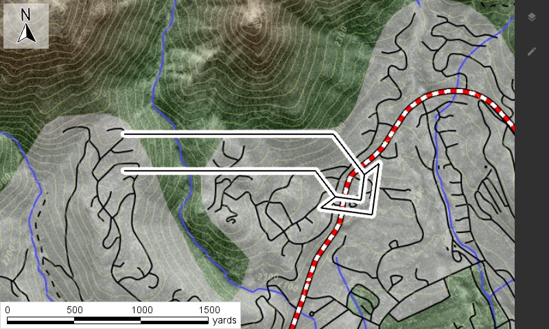
In some cases, you may not be able to use a createTool, for example if you are reading features from a file or a stream in a custom format. Let’s continue with the “Main attack line” from before which has the sidc “G-GPOLAGM—–X”. If you are not familiar with the graphic or military standard, let’s take look at the mil-std 2525C documentation to find how the graphic is define:
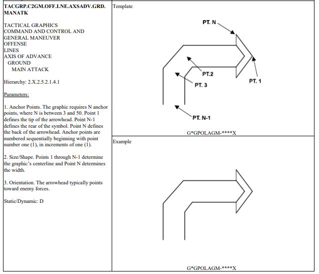
From the screenshot we can deduce the following:
width that we can deduce from the points.Based on the source format, the “Main attack” should be converted into the format expected by the TacticalVisualizer. In our case, we specify parameters with the following values:
{
sidc: "G-GPOLAGM-----X"
points: [ [ -119.97086578544294, 39.27147283887001 ], [ -119.95502563152017, 39.27105933520934 ], [ -119.95142047008808, 39.26712710205528 ] ]
width: 250.0
...
}
The SymbolStandard class can be used to retrieve metadata about a specific sidc:
auto symbolMetadata = Carmenta::Engine::SymbolStandard::milStd2525C()->metadata()->findBySidc("G-GPOLAGM-----X");
Using the information from SymbolMetadata, it is possible for a developer to implement functions that will create features based on the metadata. In our example, we can build our feature like this:
// Create the lineGeometry from list of points
Carmenta::Engine::LineGeometryPtr line = new LineGeometry();
line->points()->add(Point(-119.97086578544294, 39.27147283887001));
line->points()->add(Point(-119.95502563152017, 39.27105933520934));
line->points()->add(Point(-119.95142047008808, 39.26712710205528));

// Create the feature with the necessary attributes
Carmenta::Engine::FeaturePtr feature = new Feature(line, Crs::wgs84LongLat());
feature->attributes()->set(Atom("sidc"), "G-GPOLAGM-----X");
feature->attributes()->set(Atom("corridorAreaWidth"), 250.0); // Carmenta uses corridorAreaWidth atom internally as a way to visualize the 'width' of any corridor or look alike element

// Insert feature into a memoryDataset
Guard g(_tacticalDrawingsMemDs);
_tacticalDrawingsMemDs->insert(feature);
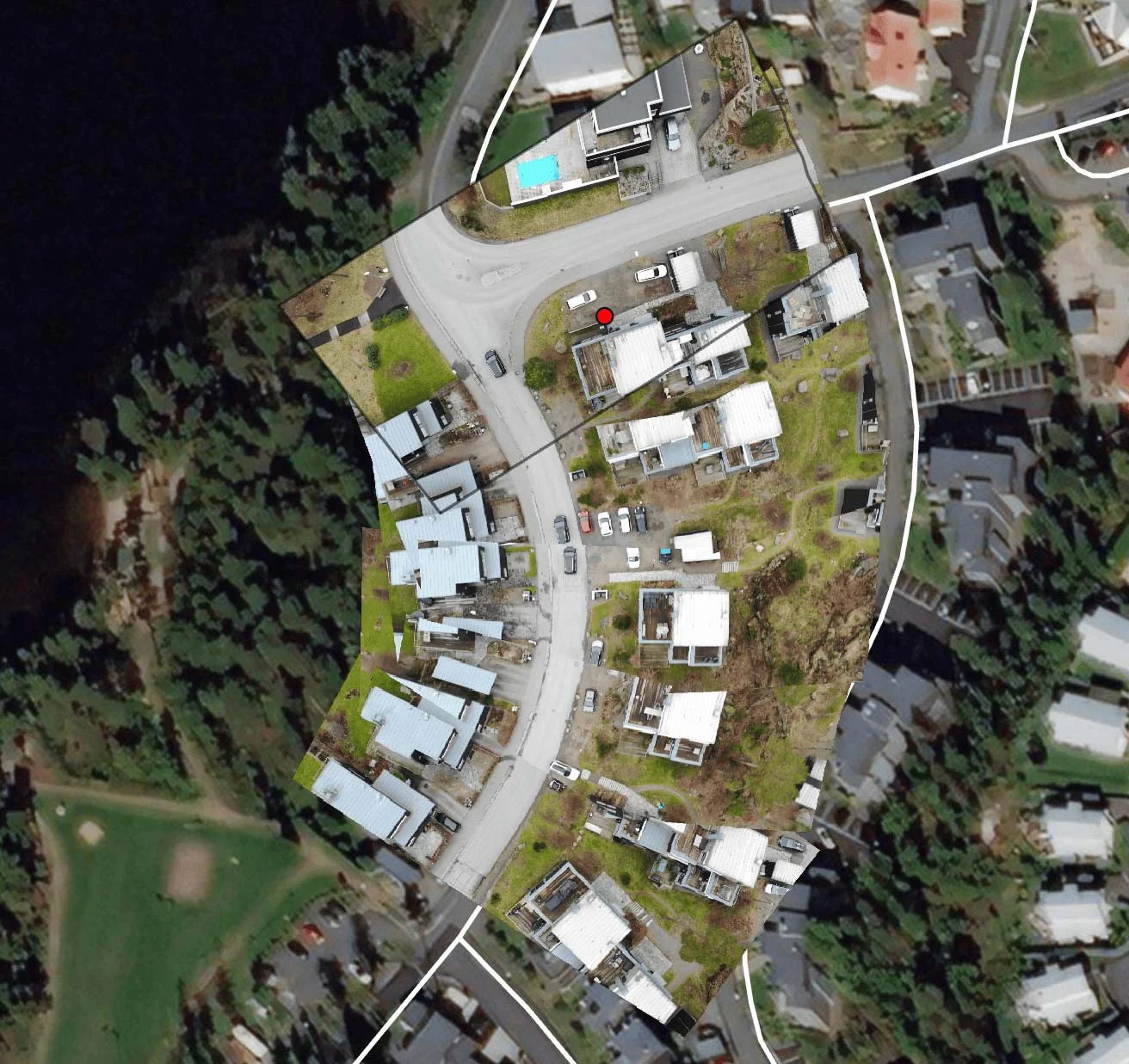
The code above will give the following result (location is over Lake Tahoe):
TacticalSymbolsExample.zip which is an application that can help browsing the mil-std catalog (only tactical symbol) and provide code sample on how to use the military standard from a createTool.Learn how to use Carmenta Engine 5.17's MosaicWriter to stitch georeferenced drone video frames into GeoPackage mosaics for real-time mapping applications.
View Post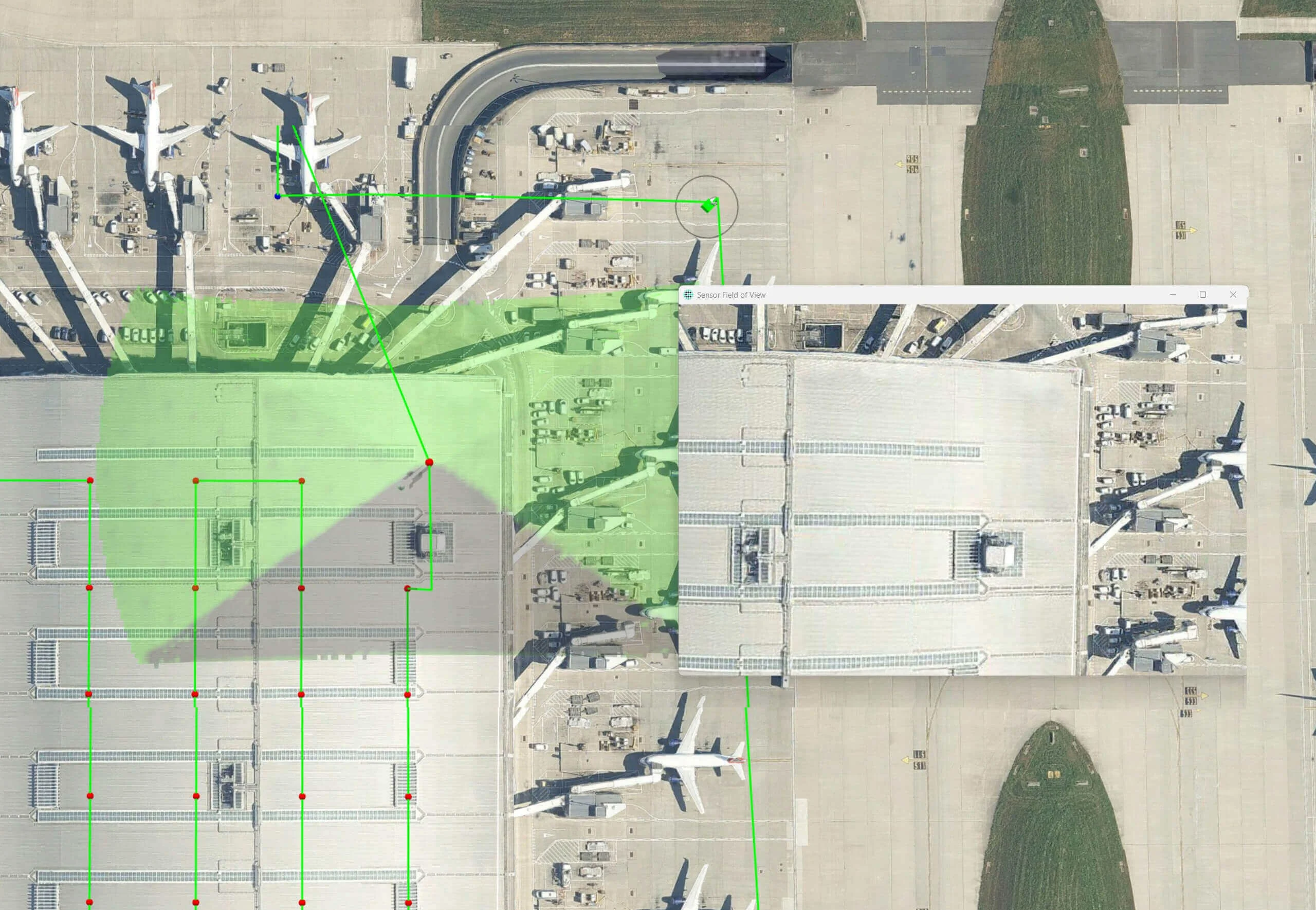
Line of Sight (LOS) analysis is critical for effective drone operations, particularly when capturing imagery for inspection or mapping.
View Post